

 English
 русский
 Español
Content
- 1 The Core Mechanism: Understanding the J-DM Hydraulic Diaphragm Working Principle
- 2 Precision Engineering: Analyzing Hydraulic Diaphragm Metering Pump Accuracy and Linearity
- 3 Built for Tough Environments: High-Pressure Diaphragm Pump Applications
- 4 The Decisive Advantage: Hydraulic Diaphragm Pumps vs. Mechanical Actuation
- 5 Ensuring Peak Performance: A Hydraulic Diaphragm Metering Pump Maintenance Guide
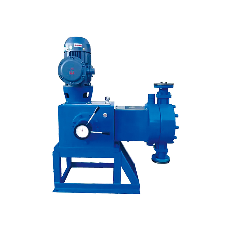
The Core Mechanism: Understanding the J-DM Hydraulic Diaphragm Working Principle
Pumps utilizing the J-DM type hydraulic diaphragm configuration represent a sophisticated solution for fluid handling, engineered around a principle of indirect actuation. The primary operation does not involve the process fluid being directly contacted by the main driving mechanism. Instead, a plunger, operating within a precisely calibrated hydraulic chamber, reciprocates back and forth, much like a standard piston pump. This plunger, however, does not pump the process chemical; it pumps a stable, non-compressible hydraulic fluid (typically oil). This hydraulic fluid, in turn, pressurizes and displaces a flexible, robust diaphragm. It is this diaphragm that serves as the barrier, separating the clean hydraulic side from the aggressive process fluid on the other side. During the suction stroke, the plunger retracts, pulling the hydraulic fluid back, which causes the diaphragm to flex inward, drawing the process fluid through an inlet check valve. On the discharge stroke, the plunger advances, pushing the hydraulic fluid against the diaphragm, flexing it outward and expelling the process fluid through an outlet check valve at a specific pressure.
Precision Engineering: Analyzing Hydraulic Diaphragm Metering Pump Accuracy and Linearity
The exceptional accuracy associated with hydraulic diaphragm metering pumps stems directly from their unique design. The use of a non-compressible hydraulic fluid as the transfer medium ensures that the movement of the plunger is translated almost perfectly into the displacement of the diaphragm. This positive displacement action guarantees that a highly precise, repeatable volume of liquid is moved with every single stroke. Furthermore, these pumps exhibit outstanding steady-state accuracy, often better than one percent, which is critical for sensitive chemical reactions or water treatment processes. The flow rate is typically controlled by adjusting the stroke length of the plunger, which can be minutely regulated, or by altering the stroke frequency (speed) via a variable frequency drive. This dual controllability allows for exceptional linearity across a wide turndown ratio, meaning the pump remains accurate whether it is operating at ten percent or one hundred percent of its maximum capacity, a feat difficult to achieve with other pump types.
Built for Tough Environments: High-Pressure Diaphragm Pump Applications
The robust construction and indirect pumping mechanism make hydraulic diaphragm pumps exceptionally well-suited for the most demanding industrial applications. Their primary advantage is the complete isolation of the process fluid. This makes them the ideal choice for pumping liquids that are highly corrosive, toxic, abrasive, or pose significant environmental hazards. In the chemical processing industry, they are indispensable for injecting catalysts, acids, bases, or polymers where any leakage would be catastrophic. Similarly, in the oil and gas sector, these pumps are employed for dosing corrosion inhibitors, hydrate inhibitors, or biocides into high-pressure pipelines, often in remote or harsh offshore environments. Water and wastewater treatment plants also rely heavily on this technology for the precise metering of disinfection chemicals like sodium hypochlorite or coagulants like ferric chloride, ensuring public safety and regulatory compliance without risking operator exposure or equipment damage.
The Decisive Advantage: Hydraulic Diaphragm Pumps vs. Mechanical Actuation
When comparing hydraulic diaphragm pumps to their mechanically actuated counterparts, the advantages of the hydraulic design become clear, particularly regarding durability and pressure handling. In a mechanically driven diaphragm pump, the diaphragm is physically attached to the plunger or drive rod, subjecting it to immense mechanical stress, stretching, and fatigue with every stroke. This limits the pressure capabilities and significantly shortens the diaphragm's operational life. Conversely, in a hydraulic design, the diaphragm is 'hydraulically balanced.' It floats between the process fluid on one side and the hydraulic fluid on the other, experiencing very little differential pressure or mechanical stress. This hydraulic support effectively protects the diaphragm from rupture, even under high-pressure discharge conditions or in the event of a suction-side blockage. This fundamental difference allows hydraulic models to operate reliably at much higher pressures and provides a significantly longer service life for the diaphragm, resulting in less downtime and lower maintenance costs.
Ensuring Peak Performance: A Hydraulic Diaphragm Metering Pump Maintenance Guide
While J-DM type hydraulic pumps are celebrated for their robust design and longevity, a proactive maintenance regimen is essential to ensure continuous, trouble-free operation. The most critical component to monitor is the hydraulic fluid itself; it should be checked periodically for the correct level, clarity, and absence of contamination. Any degradation or leakage of this fluid can compromise the pump's accuracy and the diaphragm's support. The check valves, both suction and discharge, are also vital for performance. They must be inspected for any signs of wear, clogging from slurries, or improper seating, as faulty valves are the most common cause of metering inaccuracy. Finally, while the diaphragm is built to last, it is still a wetted part subject to the process fluid. Regular visual inspection (where possible) and adherence to a preventative replacement schedule, especially when handling extremely aggressive chemicals, will prevent unexpected failures and ensure the integrity of the hydraulic system remains uncompromised. Proper calibration checks should also be performed regularly to verify that the pump's output volume remains consistent with its settings.


