English
 русский
 Español
Content
- 1 What an Axially Split Pump Is and Where It Sits in API 610
- 2 Maintenance Access: Why Axially Split Pumps Win on Turnaround Time
- 3 Pressure and Temperature Ceilings: Where the Horizontal Joint Stops Working
- 4 Materials Decide Whether the Casing Survives the Medium
- 5 Axially Split or Radially Split: A Practical Comparison
- 6 How to Specify an Axially Split Pump Correctly
- 7 Frequently Asked Questions About Axially Split Pumps
A maintenance planner at a 600,000 t/y petrochemical complex can lift the rotor out of an axially split pump and have the machine back in service inside one eight-hour shift. The same job on a radially split casing of identical duty takes two to three days, because the suction and discharge flanges, the coupling and sometimes the baseplate have to be broken before the rotor bundle can move. That three-to-one gap in turnaround time decides more pump selections than efficiency curves ever do.
The question resurfaces at every revamp, capacity upgrade and corrosive-duty replacement. Four engineering facts settle it: how the casing is split, how much pressure the bolted joint can hold, what the medium does to the metal, and how the machine will be maintained over the next twenty years.
What an Axially Split Pump Is and Where It Sits in API 610
An axially split pump is a centrifugal pump whose casing is divided on the horizontal plane through the shaft centreline, so the upper half can be lifted clear of the rotor without disturbing the suction piping, the discharge piping, the driver or the foundation.
API 610, the standard that governs refinery and petrochemical pumps, recognises two axially split families in its between-bearings range.
- BB1: one or two stages, normally with a double suction impeller, covering high-flow moderate-head duties such as crude transfer, cooling water and booster service.
- BB3: a multistage horizontally split casing with opposed impellers, carrying head that a single stage cannot while keeping top-half access.
The term is regularly confused with an axial flow pump, which moves liquid along the shaft axis with a propeller-shaped impeller. Axial flow describes the hydraulic path; axially split describes the casing joint. Mixing the two in a request for quotation produces the wrong quotation and occasionally the wrong machine on site.
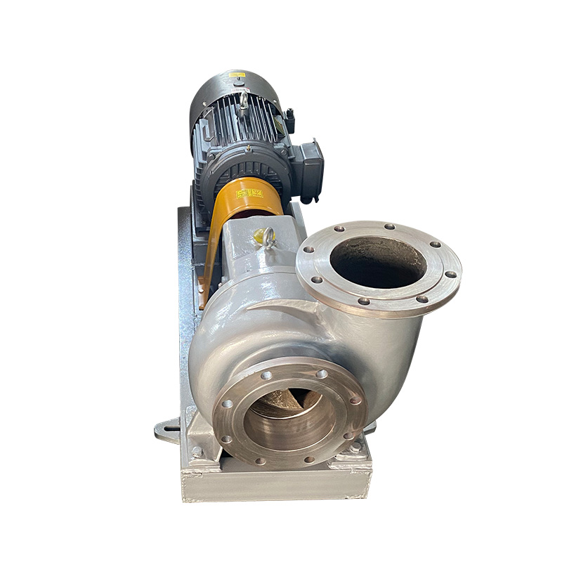
The same horizontal-joint logic makes a double suction single-stage unit practical for large circulating water and crude transfer duties.
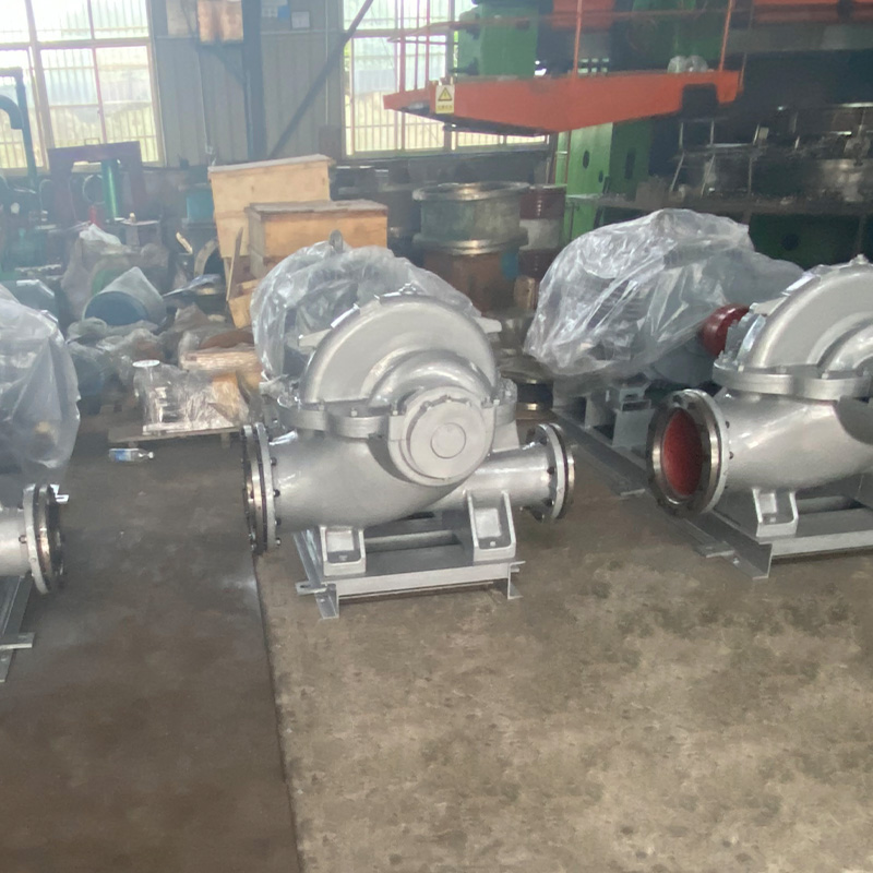 S SH Double Suction Pump for Circulating Water and Crude TransferAxially split double-suction single-stage pump suited to large circulating water and crude transfer duties, with faster rotating-element access for maintenance.View Product →
Maintenance Access: Why Axially Split Pumps Win on Turnaround Time
On a like-for-like duty, an axially split casing cuts rotating-element access time by 60 to 75 percent against a radially split casing of the same flow and head.
Three mechanical details produce that gap.
- The horizontal joint is a single bolted flange. Lifting the top half needs no pipe breaking, no laser alignment and no grout work.
- A spacer coupling lets the rotor bundle be withdrawn axially once the top half is off.
- Opposed impellers in a BB3 cancel most axial thrust hydraulically, so there is no balance drum, no balance line and one less wear part to rebuild.
The joint also punishes careless work. A spiral-wound gasket with flexible graphite filler, a controlled cross-pattern bolt tightening sequence, and a re-torque after the first heat-up cycle separate a casing that stays dry for years from one that weeps at every thermal excursion.
Plants that run a BB1 or BB3 as a spared machine usually keep a balanced rotor assembly on the shelf. Swapping a pre-balanced cartridge is a single-shift job, and the removed rotor goes to the workshop while the pump keeps running.
Pressure and Temperature Ceilings: Where the Horizontal Joint Stops Working
An axially split casing is the right answer up to roughly 40 bar for a single-stage BB1 and about 100 to 150 bar for a multistage BB3. Above that, the bolted horizontal boundary becomes the least reliable part of the machine and a radially split or barrel casing wins.
| API type | Casing split | Typical stages | Discharge pressure | Casing temperature | Typical service |
| BB1 | Axial, horizontal | 1 to 2 | up to 40 bar | up to 200 C | Cooling water, crude transfer, booster |
| BB2 | Radial | 1 to 2 | up to 100 bar | up to 400 C | Refinery charge, high-head process |
| BB3 | Axial, horizontal | 2 to 8 | 100 to 150 bar | up to 400 C | Hydrotreater feed, pipeline, boiler feed |
| BB4 | Radial, ring section | 4 to 12 | up to 250 bar | up to 450 C | Injection, descaling, high-head process |
| BB5 | Barrel | 4 to 16 | 400 bar and above | up to 450 C | Hydrocracker charge, high-pressure injection |
The reason is geometric. The horizontal joint is a continuous leak path running the full length of the casing on both sides of the shaft, roughly twice as long as a radial joint, and every additional 10 bar of discharge pressure multiplies the bolt load needed to keep the gasket compressed.
A horizontal joint is not a weak design. It is a design with a pressure ceiling, and that ceiling is set by bolt load, gasket creep and thermal cycling rather than by the impeller.
Temperature behaves the same way. Differential expansion between the upper and lower halves opens the joint slightly at every heat-up, so above roughly 200 C the gasket must be chosen for elastic recovery rather than compression alone. That is the point at which experienced engineers move to a radially split casing.
Materials Decide Whether the Casing Survives the Medium
Material selection, not the split design, decides whether the pump survives five years or five months on the same duty point.
Casings for axially split process pumps are normally supplied in one of these families.
- Carbon steel A216 WCB for water, brine and benign hydrocarbons.
- Austenitic stainless 304 and 316L for dilute acids and general chemical service.
- Duplex 2205 and super duplex 2507 where chlorides rule out 316L through stress corrosion cracking.
- CD4MCu and similar cast duplex grades for abrasive and corrosive slurries.
- Nickel alloys such as Hastelloy, plus titanium, for strong chlorides and oxidising acids.
- Heat-resistant 2520 for high-temperature process streams.
Jiangsu Huanyu Chemical New Materials Co., Ltd. has cast and machined pumps in Jingjiang since 1987 and operates its own foundry, non-metallic pressing, machining and assembly shops across more than 300 specifications. That vertical chain matters at the selection stage: the foundry confirms which grade is actually castable at the required section thickness before the order is placed, instead of discovering it at the pattern shop.
One caveat applies. If the medium is strongly acidic and the flow is modest, a fluoroplastic-lined or sealless magnetic drive pump is often cheaper and safer than a metal casing, because the wetted boundary is polymer rather than alloy. Match the casing style to the duty, never the other way round.
Axially Split or Radially Split: A Practical Comparison
Axially split casing, BB1 and BB3
- Rotor access in 6 to 14 hours
- Ceiling of 40 bar single stage, 100 to 150 bar multistage
- Strongest at high flow and moderate head
- Piping, coupling and alignment untouched during inspection
- Heavier casing per unit of pressure
Radially split casing, BB2 to BB5
- Rotor access in 28 to 50 hours
- Rated from 100 bar to 400 bar and beyond
- Strongest at high head and high pressure
- Piping and alignment work needed for major inspection
- Compact, lighter casing at high pressure
Above 150 bar, in refinery charge and hydroprocessing service, a radially split or barrel machine is the only sensible choice. On a 3000 m3/h cooling water circuit or a crude transfer line, the axially split casing wins on life-cycle cost because the maintenance saving repeats every time the machine is opened.
Where a duty sits in the middle, a back-pull-out horizontal process pump gives a compromise: the rotor comes out from the rear without breaking suction piping, although not as fast as lifting a top half.
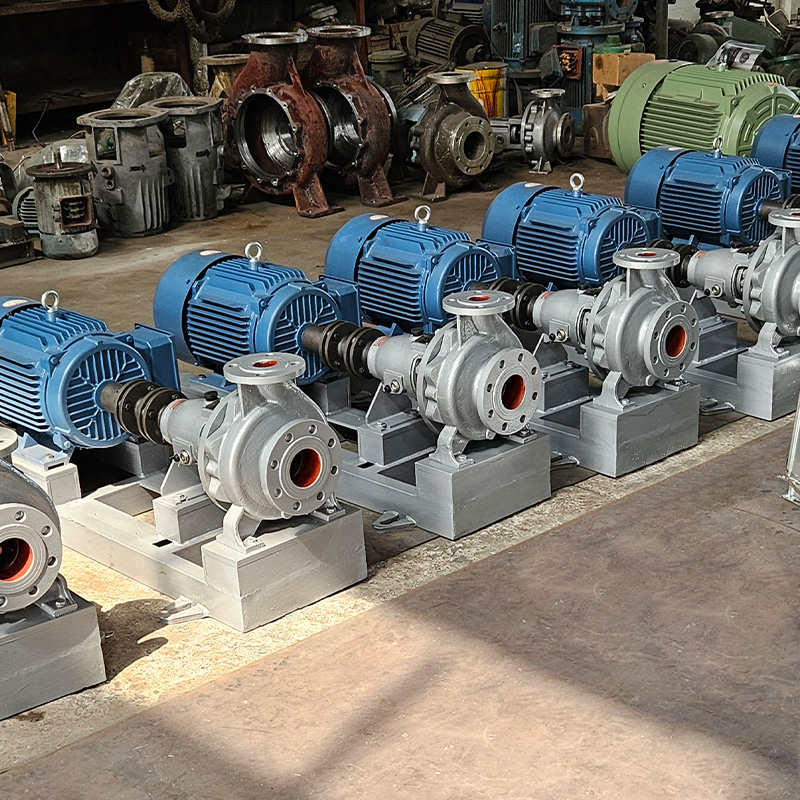 CZ Series Standard Chemical Centrifugal PumpHorizontal DIN/ISO single-stage chemical pump for neutral, corrosive, hot, cold, clean or particle-laden liquids across chemical, petrochemical, refinery, power, pharmaceutical and water-treatment duties.View Product →
How to Specify an Axially Split Pump Correctly
Six inputs decide whether an axially split pump runs for twenty years or becomes a maintenance liability.
- Fix the full operating envelope, not the rated point. Flows 20 percent above and below design change the specific speed, the impeller trim and the axial thrust balance.
- Confirm the NPSH margin at the worst operating case. A half-metre margin on paper disappears after the first suction strainer fouls.
- Choose stage count against shaft speed. Eight stages at 3600 rpm is not the same machine as four stages at 1800 rpm, even at identical head.
- Match metallurgy to the medium across every wetted part: casing, impeller, wear rings, shaft and seal chamber.
- Specify the mechanical seal and its API 682 piping plan with the pump, not after it. Seal failure, not hydraulic failure, causes most process pump outages.
- Agree the spares list and inspection interval before the order is placed. A spare rotor and a spare cartridge seal decide how long an unplanned outage lasts.
Much of this procedure carries over to the wider process pump family, and the guide on how to select a petrochemical process pump adds the checks that apply once a machine sits inside a licensed refinery unit.
Frequently Asked Questions About Axially Split Pumps
What is the difference between an axially split and a radially split pump?
The casing joint is the entire difference. An axially split casing is bolted on the horizontal centreline, so the top half lifts off and the rotor is exposed without touching the piping. A radially split casing is bolted around the vertical centreline, so the rotor comes out along the shaft axis, which on larger machines means breaking the coupling and the pipe connections.
What is the maximum pressure an axially split pump can handle?
A single-stage BB1 is normally limited to about 40 bar discharge pressure. Multistage BB3 designs run to 100 or 150 bar depending on stage count, bolt size and joint detail. Above 150 bar, barrel casings take over because the pressure boundary becomes a single cylindrical forging rather than two bolted halves.
Why do multistage axially split pumps use opposed impellers?
Opposed impellers cancel most hydraulic axial thrust inside the casing, so the thrust bearing carries only residual load and no balance drum or balance line is required. Removing those parts removes two common failure points and shortens the rotor, which makes it easier to lift out through the top-half opening.
Can an axially split pump handle aggressive chemicals?
Yes, as long as the metallurgy matches the medium. Duplex 2205, super duplex 2507, CD4MCu, Hastelloy and titanium extend the design into chloride-bearing, acidic and abrasive services. For strongly aggressive media at low flow, a fluoroplastic-lined or sealless magnetic drive pump is usually the lower-risk choice.
Have a duty point that needs checking? Send flow, head, temperature, specific gravity and medium to the engineering team through the contact page and ask for a stage count and material combination before the datasheet is frozen.